- 您现在的位置:买卖IC网 > Sheet目录1999 > ICS91305AMLF (IDT, Integrated Device Technology Inc)IC CLOCK DRIVER LO JITTER 8-SOIC
3
ICS91305
0092H—12/02/08
Notes:
1.
Guaranteed by design and characterization. Not subject to 100% test.
2.
All Skew specifications are mesured with a 50
transmission line, load teminated with 50 to 1.4V.
3.
Duty cycle measured at 1.4V.
4.
Skew measured at 1.4V on rising edges. Loading must be equal on outputs.
Absolute Maximum Ratings
Supply Voltage . . . . . . . . . . . . . . . . . . . . . . . 7.0 V
Logic Inputs (Except REF) . . . . . . . . . . . . . . GND –0.5 V to VDD + 0.5 V
Logic Input REF . . . . . . . . . . . . . . . . . . . . . . GND –0.5 V to GND + 5.5 V
Ambient Operating Temperature . . . . . . . . . . 0°C to +70°C
Storage Temperature . . . . . . . . . . . . . . . . . . . –65°C to +150°C
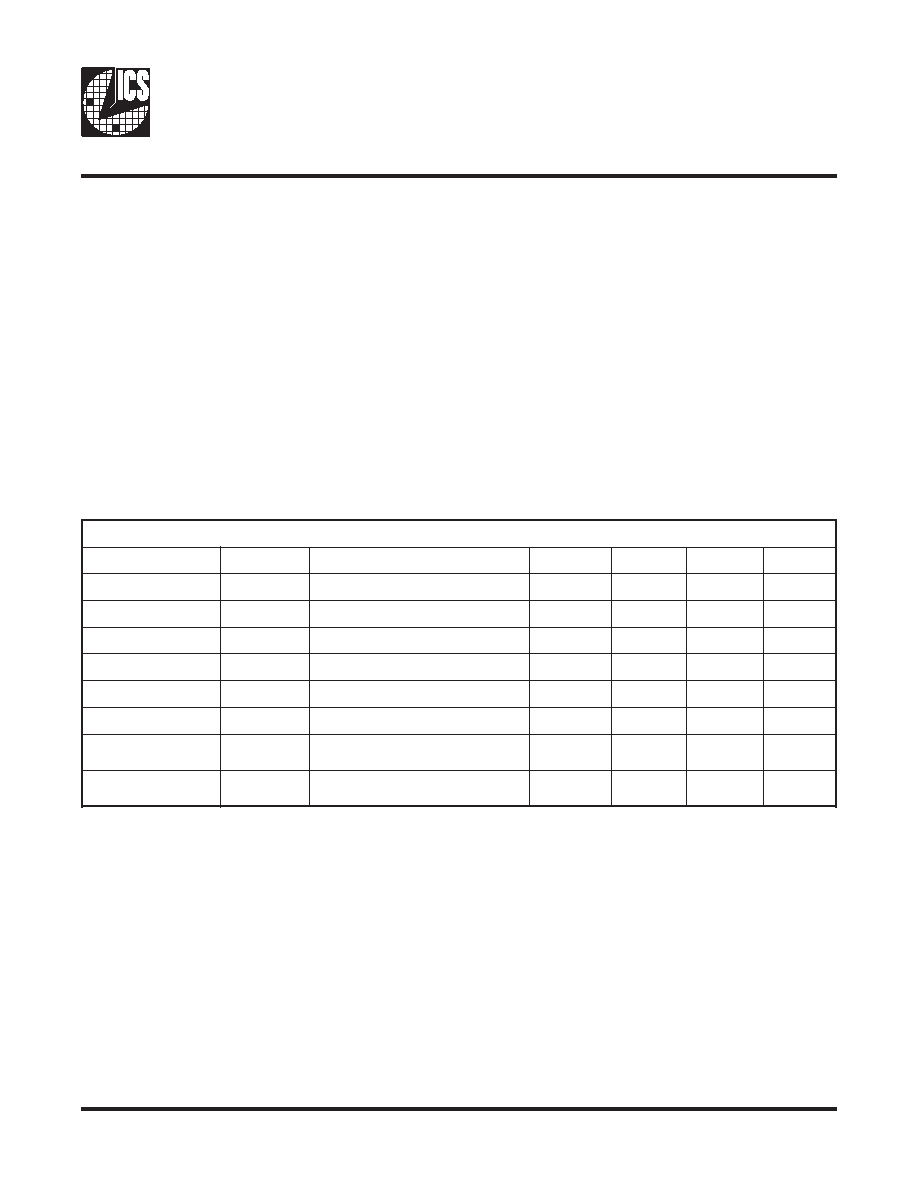
Electrical Characteristics at 3.3V
VDD = 3.0 – 3.6 V, TA = 0 – 70° C unless otherwise stated
Stresses above those listed under
Absolute Maximum Ratings may cause permanent damage to the device. These
ratings are stress specifications only and functional operation of the device at these or any other conditions above those
listed in the operational sections of the specifications is not implied. Exposure to absolute maximum rating conditions
for extended periods may affect product reliability.
s
c
i
t
s
i
r
e
t
c
a
r
a
h
C
D
R
E
T
E
M
A
R
A
PL
O
B
M
Y
SS
N
O
I
T
I
D
N
O
C
T
S
E
TN
I
MP
Y
TX
A
MS
T
I
N
U
e
g
a
t
l
o
V
w
o
L
t
u
p
n
I
V L
I
8
.
0V
e
g
a
t
l
o
V
h
g
i
H
t
u
p
n
I
V H
I
0
.
2V
t
n
e
r
u
C
w
o
L
t
u
p
n
I
I L
I
V N
I
V
0
=9
10
.
0
5A
t
n
e
r
u
C
h
g
i
H
t
u
p
n
I
I H
I
V N
I
V
=
D
0
1
.
00
.
0
1A
e
g
a
t
l
o
V
w
o
L
t
u
p
t
u
O
1
V L
O
I L
O
A
m
5
2
=5
2
.
04
.
0V
e
g
a
t
l
o
V
h
g
i
H
t
u
p
t
u
O
1
V H
O
I H
O
A
m
5
2
=4
.
29
.
2V
y
l
p
u
S
n
w
o
D
r
e
w
o
P
t
n
e
r
u
C
I D
D
z
H
M
0
=
F
E
R3
.
00
.
0
5A
t
n
e
r
u
C
y
l
p
u
S
I D
D
z
H
M
6
.
6
t
a
s
t
u
t
u
o
d
e
d
a
o
l
n
U
V
t
a
s
t
u
p
n
i
L
E
S
D
N
G
r
o
0
.
0
30
.
0
4A
m
发布紧急采购,3分钟左右您将得到回复。
相关PDF资料
ICS91309AGILF
IC CLK BUFFER ZD PLL 16TSSOP
ICS9161A-01CW16T
IC FREQUENCY GENERATOR 16-SOIC
ICS91730AMLF
IC CLOCK GENERATOR LOW EMI 8SOIC
ICS9173B-15CS08LF
IC PLL VIDEO GENLOCK 8SOIC
ICS9248BF-138LFT
IC FREQ GENERATOR/BUFFER 48-SSOP
ICS9250BF-12LF
IC FREQ TIMING GENERATOR 56-SSOP
ICS9250BF-28
IC FREQ GENERATOR/BUFFER 56-SSOP
ICS9250CF-10LF
IC FREQ TIMING GENERATOR 56-SSOP
相关代理商/技术参数
ICS91305AMLFT
功能描述:IC CLOCK DRIVER LO JITTER 8-SOIC RoHS:是 类别:集成电路 (IC) >> 时钟/计时 - 时钟发生器,PLL,频率合成器 系列:- 标准包装:2,000 系列:- 类型:PLL 时钟发生器 PLL:带旁路 输入:LVCMOS,LVPECL 输出:LVCMOS 电路数:1 比率 - 输入:输出:2:11 差分 - 输入:输出:是/无 频率 - 最大:240MHz 除法器/乘法器:是/无 电源电压:3.135 V ~ 3.465 V 工作温度:0°C ~ 70°C 安装类型:表面贴装 封装/外壳:32-LQFP 供应商设备封装:32-TQFP(7x7) 包装:带卷 (TR)
ICS91305AMT
功能描述:IC CLOCK DRIVER LO JITTER 8-SOIC RoHS:否 类别:集成电路 (IC) >> 时钟/计时 - 时钟发生器,PLL,频率合成器 系列:- 标准包装:2,000 系列:- 类型:PLL 时钟发生器 PLL:带旁路 输入:LVCMOS,LVPECL 输出:LVCMOS 电路数:1 比率 - 输入:输出:2:11 差分 - 输入:输出:是/无 频率 - 最大:240MHz 除法器/乘法器:是/无 电源电压:3.135 V ~ 3.465 V 工作温度:0°C ~ 70°C 安装类型:表面贴装 封装/外壳:32-LQFP 供应商设备封装:32-TQFP(7x7) 包装:带卷 (TR)
ICS91305I
制造商:ICSI 制造商全称:Integrated Circuit Solution Inc 功能描述:High Performance Communication Buffer
ICS91305YGILF-T
制造商:ICSI 制造商全称:Integrated Circuit Solution Inc 功能描述:High Performance Communication Buffer
ICS91305YGLFT
制造商:ICS 制造商全称:ICS 功能描述:High Performance Communication Buffer
ICS91305YMILF-T
制造商:ICSI 制造商全称:Integrated Circuit Solution Inc 功能描述:High Performance Communication Buffer
ICS91305YMLFT
制造商:ICS 制造商全称:ICS 功能描述:High Performance Communication Buffer
ICS91309
制造商:ICS 制造商全称:ICS 功能描述:High performance Communication Buffer